Confirm the instrument-truck supply boundary
Define the selected tools, line and deployment method, depth and load basis, acquisition channels and required output records for the actual well program. The proposed truck configuration should identify its carrier, installed deployment equipment, operator workspace and power arrangement. Ask the supplier to list supported interfaces and limitations instead of assuming universal instrument compatibility from the product name.
External wellhead and pressure-control equipment require their own competent selection and acceptance. Surface separators, flow meters and effluent handling are separate package responsibilities unless explicitly included in the accepted offer. Any required data connection to those systems needs an identified interface and verification plan. Retain that boundary with the purchase, factory evidence and site handover records.
Begin with the real operating basis
A useful Test Well Truck plan starts with the work the unit must perform: mobile instrument deployment, depth measurement and data acquisition for an accepted well-survey program. Record normal, minimum, maximum and transient cases instead of relying on one headline capacity. The review should identify selected tools and line requirements, accepted depth and load conditions, tool measurement and data requirements, external wellsite interface requirements and measurement evidence and output requirements together with the source and confidence level for each value.
Trace those inputs through the line-handling and winch arrangement, depth measurement and instrument interfaces, installed power and control arrangement and surface data-acquisition and operator workspace. This system view helps the project team see where a site condition, fluid property or operating limit affects more than one component. It also creates a defensible basis for supplier clarification, field setup and later change control.
Describe every fluid the equipment can encounter
Provide composition, concentration, density, viscosity, solids, particle size, gas content, water chemistry, pH, chlorides, hydrogen sulfide or other hazardous constituents, and expected contamination. State normal and cleaning fluids as well as upset fluids. Temperature, pressure and exposure time must accompany the chemistry because material performance depends on the complete service condition.
| Review point | Project question | Required record |
|---|---|---|
| line-handling and winch arrangement | Accepted tool, line, working duty and installed access | Configuration-specific deployment response |
| depth measurement and instrument interfaces | Measurement basis, instrument compatibility and record identity | Interface schedule and verification evidence |
| installed power and control arrangement | Installed loads, supply conditions and documented functions | Power arrangement and function schedule |
| surface data-acquisition and operator workspace | Required channels, outputs, workspace and service access | Acquisition schedule and installed layout |
Check elastomers, seals and small wetted parts
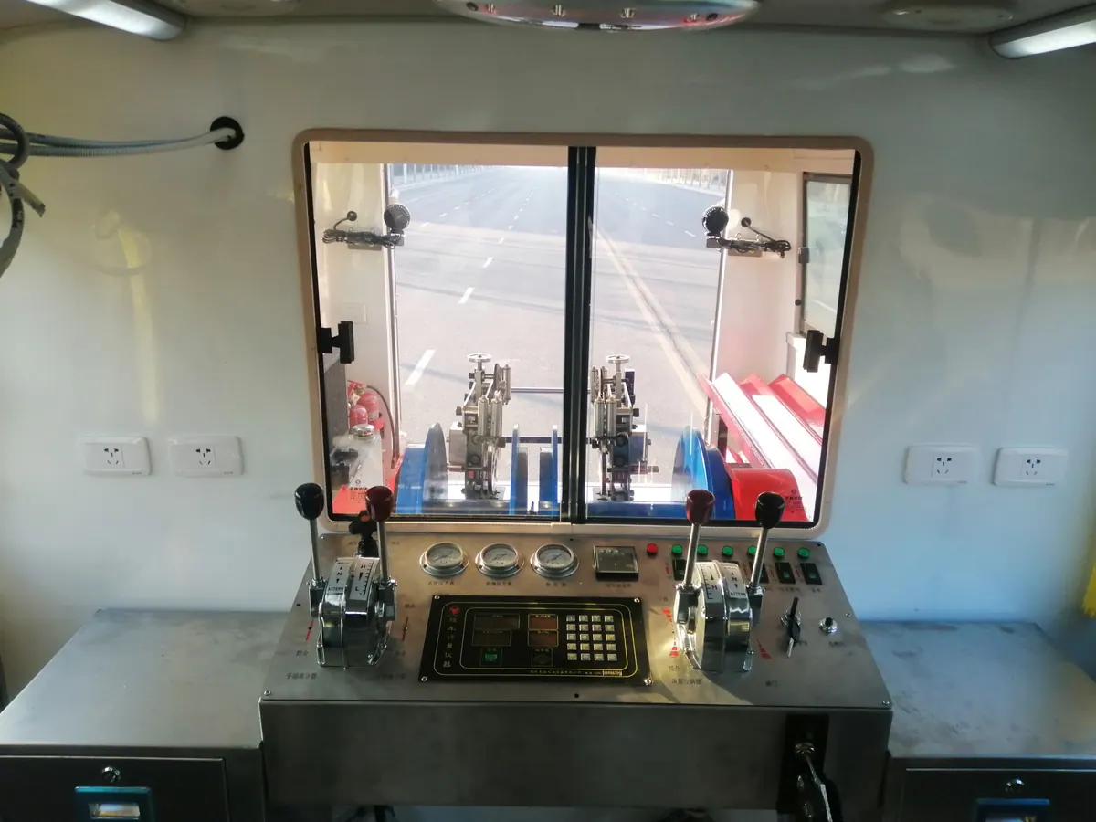
Separate the selected downhole tools and external pressure equipment from the truck hydraulic system and other installed components. Ask each responsible supplier to identify exposed materials, seals, hoses and interfaces within its actual scope. A cabin or winch photograph is not evidence of suitability for produced-fluid contact. Ask the supplier to identify these items by material rather than by trade name alone. Review swelling, hardening, permeation, temperature cycling, decompression and abrasive wear where relevant.
Different instrument programs can expose tools and separately supplied equipment to different well environments. Review those conditions with the relevant manufacturers instead of assuming that one accepted tool or hydraulic-fluid choice establishes universal truck compatibility. Approve each service case and define whether flushing, neutralization, drying or seal replacement is required before changing duties.
Turn compatibility claims into controlled evidence
Record the approved fluid envelope, material list, supplier limitations, inspection points and replacement criteria. When laboratory testing is needed, reproduce the realistic concentration, temperature, pressure and exposure duration. A short ambient soak does not demonstrate suitability for hot, pressurized or cyclic field service. Keep the decision with the equipment file so later substitutions can be reviewed against the same basis.
Keep records that support the next decision
Keep the approved duty sheet, site survey, interface drawing, procedures, inspection results, test records, deviations and signed handover information in one controlled equipment file. Record the installed component models and document revisions so operators and maintenance personnel can confirm that their instructions match the field configuration.
After the job, compare planned and actual values for selected tools and line requirements, accepted depth and load conditions, tool measurement and data requirements, external wellsite interface requirements, measurement evidence and output requirements. Record abnormal events, adjustments, consumable use and any condition that affected setup or performance. Use the findings to improve the next job plan without silently expanding the approved operating envelope.
Apply project and jurisdictional requirements
Use this planning guide with the owner's procedures, local law and applicable project standards. Review relevant requirements through OSHA oil and gas extraction safety guidance. The project-specific engineering and safety basis governs the final configuration and work method.